Skip to content
Whenever a typhoon hits, outdoor street light poles must withstand a rigorous test of wind resistance. With the advancement of urban modernization, metal pole street lights have replaced concrete pole street lights, which have become the mainstream of road lighting facilities, street light lines are also shifted from overhead lines to buried cable laying.
The construction of a metal pole street light has relatively strict strength requirements for the construction of the foundation of the street light, involving the foundation bolts, the strength of the foundation concrete itself, the compaction of the surrounding soil around the foundation, and several other aspects of safety calculations.
In this article, the design size and strength of the foundation bolts of the street light are calculated for safety checks, a thorough analysis is conducted to identify the reasons behind the tilting of the street light, examining the factors systematically.
1. Operating conditions assumptions
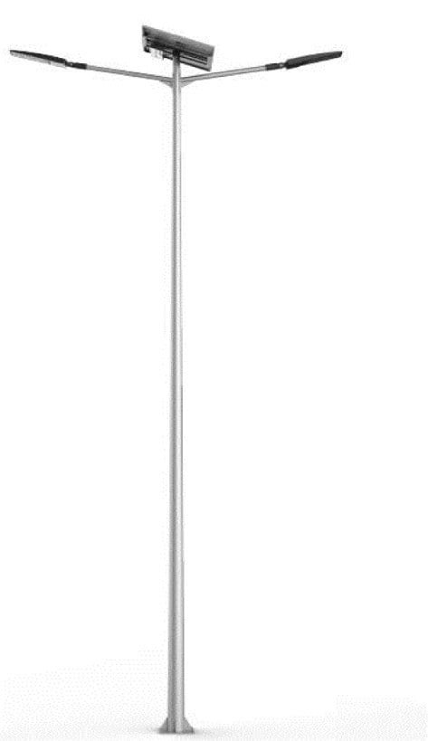
We assume a set of conventional single bent arm street lights with a height of 10m (vertical height from the centerline of the lamp to the plane of the foundation flange) and a wind resistance level of 12-grade typhoon. The foundation is a standard 1.2m conventional foundation, the flange size of the lamp pole is 400*400mm, the flange size of the foundation is 600*600mm, the foundation bolts is 4*M20, the center distance of the bolts is 260mm, the lamp pole and foundation bolts are Q235 steel, the bottom outer diameter of the lamp pole is 208mm, the top diameter is 100mm. Meet the strength requirement of no deformation or damage under the limit of 12-grade typhoons, the flange of the lamp pole and the foundation flange can not be deformed and damaged under extreme conditions, and the foundation pit is stable. The detailed structure diagram of the light pole and foundation is as follows:
2. The light pole force analysis
2.1、Simplification of force diagram
According to the analysis of material mechanics, we can see that the street light pole is subjected to a single tensile force on all four fixed bolts on the contact surface of the base flange before the tilt of the light pole occurs, and only after the tilt of the light pole occurs does it produce a mountain of torque and shear force on the base bolts. The limiting case of the force is in the direction of the airflow passing horizontally along the pick arm. The overturning moment caused by the weight of the pick arm and luminaire has little effect on the foundation of the pole for the time being. It can be seen that the pivot point of the light pole is at the edge of the flange below the light pole, which is marked by a triangle in the figure. The force diagram of the light pole is simplified as follows:

2.2、Force analysis
The wind speed is V=36.9m/s and the wind pressure is
P=V2/ 1.6=851.01N/m2.The light pole is tapered and the wind area is
S1=(D+d)*H/2=(0. 18+0.068)*10/2= 1.24m2.
The wind area of the lamp is about S2=0.3m2. The torque of the typhoon airflow on the light pole varies with the cross-section of the pole and the height. and different heights, so the approximate calculation is used here. The wind force on the base of the force point approximation for the upper and lower windward area of the position of equal force, according to the calculation of this
position from the base flange of the lamp pole distance L1 = 2.93m, the lamps affected by wind force distance L2 = 10m, assuming that each bolt is subject to the pull force F, according to the action and reaction force, the bolts to the flange of the pull force is also F, can be obtained as Figure 4 of the force analysis diagram, where Fa = Fb = F.
2.3、Force calculation of foundation bolts
The moment generated by the wind force on the light pole is M wind = F1*L1 = P*S1*L1 = 851.01*1.24*2.93 = 3091.89 N-m
The moment generated by the wind force on the lamp is M lamp = F2*L2 = P*S2*L2 = 851.01*0.3*10 = 2553.03N-m
The pulling moment of the bolts on the flange of the lamp post is M bolts = 2Fa*La+2Fb*Lb=2Fa*0.2825+2Fb*0.0747
According to the moment balance, M bolts = M wind + M light
According to the force analysis, the bolts are equally stressed, Fa = Fb The final single bolts force F=7901.62N is obtained
3. the actual force limit calculation of the foundation bolts
According to the conditions, the base bolts material Q235, the design tensile strength of 215MPa, check the design manual, M20 small diameter of 17.29mm, can be calculated M20 bolts effective cross-sectional area of πr2 = 234.79mm2, so the allowable tensile force is
F Xu = 215 * 234.79 = 50.480KN, that is, the role of the tension on a single bolt more than F Xu may turn from elastic deformation to plastic deformation, resulting in necking at the weakest position, necking to a certain extent will produce fracture damage. For the light pole foundation, the moment plastic deformation occurs, the force on the foundation bolts from a single tensile into a combination of tension and bending, which will accelerate the progress of bolt damage.
4. The base bolts safety identification
According to the above calculation, the street light in the case of suffering level 12 typhoons, the actual instantaneous tension of the foundation single bolts are much smaller than the permissible tension of the foundation bolts F Xu, that is, F
5. Common Street Light Tilt Cause Analysis
Through a number of city street light research, we often find that the original construction phase is debugged in place after a year or two of operation, the phenomenon of tilting the pole, the pole tilted to a certain extent after the basic can not see signs of continued expansion unless the impact of bad weather will be further tilted or even the phenomenon of tipping the pole. But the construction of street lights in the elevated retaining wall never appears to be a tilted phenomenon, even if the street light pole was hit and broken the root of the street light pole flange is still firmly fixed in the foundation flange—analysis of the reasons, no more than the following aspects.

5.1, foundation reasons. We know that usually the road lighting project is followed by the simultaneous construction of road projects, new roads in the machine non-separated or central green belt generally need to go through the process of excavation and backfill of green soil, the new backfill of green soil generally only do leveling, not compaction treatment, and street light lamp design will generally choose these two places, which leads to new street light pit excavation and foundation production completed (either prefabricated or cast-in-place), the soil compaction around the foundation can not meet the requirements, and the general street light construction will rarely be fully compacted for the foundation location soil, which leads to the installation of street lights in place, with the foundation around the soil settlement and street lights affected by wind constantly shaking, the pole began to slowly tilt to one side. In the sidewalk or pavement installed street lights, because the sidewalk roadbed is a certain compaction treatment, paving will also play a certain role in stabilizing the foundation around the completion, so the street lights installed in these places rarely skewed phenomenon.
5.2, the foundation causes. Due to the foundation itself, the concrete strength is not strong enough to lead to foundation cracking, the bolts in the foundation concrete are loose, and the foundation gasket is not fixed firmly to lead to running, these can lead to the foundation bolts loose, rotate or even be pulled out of the phenomenon.
5.3, bolts causes. The Anchor bolts led to a less skewed light pole, the general reason is that the bolt nut fastening is not in place or not set shims and double nuts as required, there are cases of brutal construction that led to one or two of the bolts fracturing after not doing remedial measures, rarely because the bolts design strength is not enough to cause the bolts to pull off, but individual construction or construction units to save investment using too thin bolts or poor quality bolts, coupled with the late Maintenance is not in place, the bolts rust serious, will bring the street light pole in the case of impact force instantly fall to the ground causing serious consequences.
5.4, the foundation flange reasons. This cause is also more common, manifested as the foundation flange thickness is not enough, not reaching the design size, or mortar encapsulation too much not over the foundation flange, these will cause the light pole instability.
6. the significance of the force analysis of the foundation bolts
After the street light foundation bolts for force analysis, we can introduce the concept of safety factor from the design point of view, by consulting the mechanical design manual or related tools, you can quickly select the appropriate bolt design size, in order to ensure the quality of the design at the same time, to ensure the safety of the operation of street lights. At the same time, not very high street lamp pole foundation design, can be calculated under the premise of safety, the choice of small bolt size, thereby saving construction costs and reducing the waste of resources, especially in the community garden lights foundation design, the significance of more. Of course, only the strength of the street lamp bolts is far from guaranteeing the safety of street lamp operation, but also the need for street lamp foundation size and concrete strength to ensure that the foundation itself can meet the requirements of safe operation, and at the same time to calculate the foundation and the compaction of the backfill around the pit, to give a clear foundation around the compaction requirements and can not meet the case of the foundation reinforcement measures, so as to guide the construction. With these three types of safety calculations, the construction drawings for lighting design will be more fleshed out, more comprehensive, and safer.
Conclusion
In this paper, particular attention is given to the strength of the foundation bolts of the street light, highlighting the significance of verifying the foundation’s safety. Additionally, an analysis of the common reasons for pole skewing during street light construction is undertaken to enhance overall understanding and prevent potential issues.
Further analysis is then conducted by calculating average illuminance, power density, and line pressure drop, among other factors to ensure that the chosen lighting design standards are met. This includes a detailed examination of the lamp pole structure, foundation support design, and lamp support design, ensuring compliance with standard specifications. Safety checks are also performed, addressing the strength of the lamp pole, foundation strength, foundation bolt strength, and foundation soil quality. However, it is important to note that these safety checks are not exhaustive. To learn more about solar street lighting design, please read my other article, 5Tips For Choosing Solar Street Light Poles, How to design and calculate a solar street light system? , Reveal How To Make Solar Street Lights?